


Author: ITCT Network Engineering Team | Hardware Review & Guide Last Updated: December 28, 2025 | Reading Time: 10 Minutes
::: tip Quick Answer: Why 400G is Critical for AI? In AI training, the network is the computer. 400G optical transceivers (like the Mellanox MMA4Z00-NS400) enable the massive bandwidth required to synchronize gradients between thousands of GPUs. Without 400G NDR (InfiniBand) or 400GbE (Ethernet), even the fastest H100/H200 GPUs will sit idle waiting for data.
- Best for Latency: 400G InfiniBand (NDR)
- Best for Flexibility: 400G Ethernet (RoCEv2) :::
Key Takeaways for Network Architects:
- The Technology: Understanding PAM4 modulation and why it changed the game for high-speed optics.
- Product Deep Dive: Technical specs of the NVIDIA Mellanox MMA4Z00-NS400.
- Deployment Guide: How to choose between OSFP and QSFP-DD form factors.
- Troubleshooting: Essential tips for fiber inspection and thermal management in high-density racks.
(This guide explains the physical layer connectivity that powers modern AI supercomputers, based on current IEEE 802.3bs standards and NVIDIA networking specifications.)
The explosive growth of artificial intelligence workloads has fundamentally transformed data center networking requirements. Modern AI training clusters demand unprecedented bandwidth, minimal latency, and zero packet loss to fully utilize expensive GPU computing resources. At the heart of this infrastructure revolution lies 400G optical transceiver technology—the critical component enabling high-speed connectivity between compute nodes, switches, and storage systems.
400G optical transceivers for AI networks
400G optical transceivers represent a quantum leap over previous 100G and 200G generations, delivering the bandwidth density required by today’s AI workstations and GPU servers. These advanced modules enable organizations to build high-performance networks that eliminate bottlenecks which would otherwise leave expensive GPUs starved for data. As training datasets grow to petabyte scale and models expand to trillions of parameters, 400G connectivity has transitioned from luxury to necessity for serious AI infrastructure deployments.
This comprehensive guide explores the technical architecture, deployment considerations, and strategic value of 400G optical transceivers in AI network environments. We examine leading solutions including the Mellanox MMA4Z00-NS400, analyze integration with InfiniBand switches, and provide practical guidance for GPU cluster design incorporating these advanced networking components.

Understanding 400G optical transceivers for AI networks
Architectural Evolution and Standards
400G optical transceivers represent the culmination of decades of innovation in fiber optic communication technology. These modules employ sophisticated modulation techniques, advanced signal processing, and precision optical components to achieve data rates that seemed impossible just years ago.
The IEEE 802.3bs standard, ratified in 2017, established the technical foundation for 400 Gigabit Ethernet. This standard defines multiple physical layer specifications optimized for different reach requirements, from short-range multimode connections within a single rack to long-haul single-mode links spanning tens of kilometers. The flexibility of the 400G standard enables deployment across diverse use cases while maintaining interoperability between equipment from different vendors.
Modern 400G transceivers predominantly utilize the QSFP-DD (Quad Small Form-factor Pluggable Double Density) or OSFP (Octal Small Form-factor Pluggable) form factors. QSFP-DD maintains backward compatibility with previous QSFP generations while doubling electrical lane count from four to eight, each operating at 50 Gbps using PAM4 (Pulse Amplitude Modulation 4-level) signaling. This architecture delivers 400 Gbps aggregate bandwidth in a compact, hot-swappable package compatible with existing data center infrastructure.
PAM4 Modulation Technology
The transition to PAM4 modulation represents one of the most significant technological advances enabling 400G performance in practical form factors. Unlike traditional NRZ (Non-Return-to-Zero) signaling which encodes one bit per symbol, PAM4 encodes two bits per symbol by utilizing four distinct amplitude levels. This approach effectively doubles data rate without requiring proportional increases in baud rate or electrical bandwidth.
PAM4’s multi-level signaling comes with important trade-offs. The reduced spacing between signal levels decreases noise immunity compared to NRZ, requiring more sophisticated error correction and signal processing. Modern 400G transceivers incorporate forward error correction (FEC) algorithms specifically designed for PAM4, enabling reliable operation despite reduced signal-to-noise ratios. The KP4 FEC standard commonly deployed in 400G systems provides robust error correction while adding minimal latency—critical for AI workloads sensitive to network delays.
400G optical transceivers for AI networks
Optical Variants and Reach Categories
400G transceivers are available in numerous optical variants optimized for specific reach requirements and cable types:
SR8 (Short Reach 8-lane): Utilizes 850nm VCSEL (Vertical Cavity Surface Emitting Laser) technology over multimode fiber, supporting distances up to 100 meters. This variant serves as the workhorse for intra-rack and short-distance rack-to-rack connections in AI data centers. The eight parallel optical lanes map directly to the eight electrical lanes of QSFP-DD, simplifying transceiver design and reducing cost compared to wavelength multiplexed alternatives.
DR4 (Double Reach 4-lane): Employs four wavelengths over single-mode fiber, extending reach to 500 meters. DR4 utilizes 1310nm wavelength region and delivers excellent performance for connections spanning multiple rows in large data centers. This variant provides an optimal balance of reach, cost, and power consumption for many AI cluster deployments.
FR4 (Four-lane Full Reach): Extends single-mode transmission to 2 kilometers using four wavelengths in the 1310nm region with CWDM (Coarse Wavelength Division Multiplexing) technology. FR4 enables connections between buildings on a campus or between data halls in mega-scale facilities, supporting disaggregated AI infrastructure architectures where compute, storage, and networking resources reside in separate physical locations.
LR4 (Long Reach 4-lane): Provides 10 kilometer reach over single-mode fiber using four CWDM wavelengths. LR4 transceivers support metro-area connections, enabling distributed AI training across multiple data center sites or connectivity to remote storage repositories containing training datasets.
ER8 (Extended Reach 8-lane): Pushes reach to 40 kilometers using eight wavelengths with LWDM (LAN Wavelength Division Multiplexing) technology. This variant enables truly distributed AI infrastructure spanning metropolitan areas, supporting use cases like federated learning where training data cannot be centralized due to privacy, sovereignty, or bandwidth constraints.
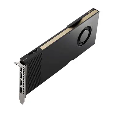
Mellanox MMA4Z00-NS400: NDR InfiniBand Excellence
Technical Architecture and Capabilities
The Mellanox MMA4Z00-NS400 represents NVIDIA’s flagship optical transceiver for NDR (Next Data Rate) InfiniBand deployments operating at 400 Gbps per port. This OSFP-format module delivers the extreme performance characteristics required by the world’s fastest supercomputers and largest-scale AI training clusters.
InfiniBand’s architectural advantage over Ethernet stems from its purpose-built design for high-performance computing workloads. Unlike Ethernet which evolved from office networking, InfiniBand was engineered from inception to deliver ultra-low latency, lossless transmission, and efficient remote direct memory access (RDMA). These characteristics prove essential for AI training where gradient synchronization operations generate massive amounts of network traffic with strict latency requirements.
| Specification | Mellanox MMA4Z00-NS400 Details |
|---|---|
| Form Factor | OSFP (Octal Small Form-factor Pluggable) |
| Data Rate | 400 Gbps (8x 50 Gbps lanes) |
| Protocol | InfiniBand NDR |
| Wavelength | 850nm (VCSEL array) |
| Fiber Type | MMF OM3/OM4/OM5 |
| Connector | MPO-12 (12-fiber) |
| Maximum Reach | 100m (OM3), 150m (OM4/OM5) |
| Power Consumption | <12W typical |
| Operating Temperature | 0°C to 70°C |
| Latency | <100ns transceiver contribution |
The MMA4Z00-NS400 utilizes parallel optics architecture with eight independent VCSEL transmitters and photodetector receivers, each operating at 50 Gbps. This parallel approach maximizes reliability by eliminating single points of failure—if one lane experiences issues, the transceiver can automatically disable the affected lane and redistribute traffic across remaining healthy lanes, maintaining connectivity albeit at reduced bandwidth.
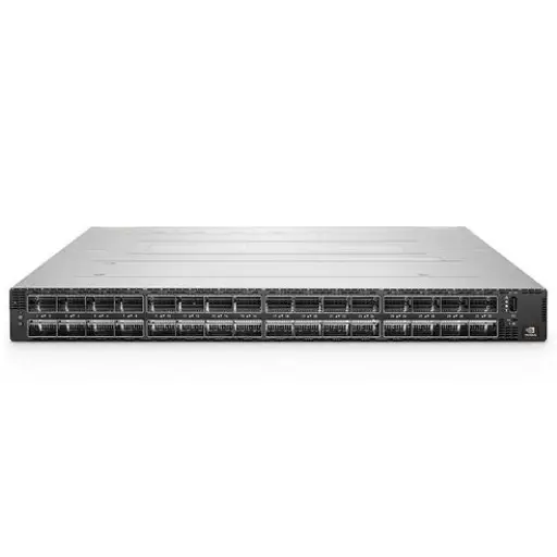
Integration with NVIDIA InfiniBand Switches
The MMA4Z00-NS400 integrates seamlessly with NVIDIA’s InfiniBand switch portfolio, including the Quantum-2 QM9700 and QM9790 platforms. These switches provide the spine and leaf infrastructure for large-scale AI fabrics, with the QM9790 delivering 64 ports of 400G NDR connectivity in a single 1U chassis—an unprecedented level of bandwidth density.
When deploying MMA4Z00-NS400 transceivers in an InfiniBand fabric, organizations benefit from advanced features built into the protocol:
Adaptive Routing: InfiniBand’s adaptive routing dynamically selects optimal paths through the network based on current congestion levels. This capability proves invaluable in AI training clusters where traffic patterns vary dramatically throughout training iterations. During gradient all-reduce operations, adaptive routing distributes traffic across available paths, preventing hotspots that could throttle throughput.
Credit-Based Flow Control: Unlike Ethernet’s reactive flow control which triggers after congestion occurs, InfiniBand employs proactive credit-based mechanisms that prevent packet loss before buffers overflow. Each receiver allocates buffer credits to senders, who can only transmit when sufficient credits are available. This approach guarantees lossless operation essential for RDMA protocols that AI frameworks depend upon.
Low Latency Profile: The MMA4Z00-NS400 adds less than 100 nanoseconds of latency to data transmission—a negligible overhead compared to switch forwarding delays. This minimal latency contribution ensures that the optical layer doesn’t become a bottleneck in latency-sensitive AI workloads. Combined with InfiniBand’s sub-microsecond switch latency, end-to-end network delays remain well below thresholds that would impact GPU training performance.
Deployment Considerations for AI Workloads
Successfully deploying MMA4Z00-NS400 transceivers requires attention to several critical factors:

Fiber Infrastructure Selection: While the transceiver supports OM3, OM4, and OM5 multimode fiber, organizations building new infrastructure should standardize on OM4 or OM5 for maximum reach and future-proofing. OM4 provides 150-meter reach at 400G—sufficient for most data center deployments—while OM5 offers additional margin through wider effective modal bandwidth. The incremental cost of OM5 over OM3 remains modest relative to total infrastructure investment, making it the preferred choice for greenfield deployments.
MPO Connector Quality: The MPO-12 connectors used with parallel optics transceivers demand meticulous attention to cleanliness and physical condition. Even microscopic contamination on fiber end faces can degrade optical performance, increasing bit error rates and potentially causing link failures. Organizations should implement rigorous fiber inspection protocols using automated inspection equipment, maintaining documentation of connector condition throughout the infrastructure lifecycle.
Power and Thermal Management: Each MMA4Z00-NS400 transceiver dissipates approximately 12 watts under typical operating conditions. In a fully populated NVIDIA Quantum-2 QM9790 switch with 64 ports, transceiver power consumption alone approaches 768 watts—nearly as much as the switch itself. Data center designers must account for this thermal load in cooling system capacity planning. Front-to-back or back-to-front airflow alignment between transceivers and switches ensures efficient heat removal without creating recirculation zones that could cause thermal hotspots.
Inventory and Sparing Strategy: Organizations deploying hundreds or thousands of 400G transceivers should maintain strategic spare inventories to minimize downtime from failed modules. While modern transceivers demonstrate excellent reliability, failures do occur, and having spares on-site eliminates shipping delays when replacements are needed. A spare pool equivalent to 3-5% of deployed transceiver count typically provides adequate coverage for most environments while avoiding excessive capital tied up in unused inventory.

InfiniBand Switches: The Fabric Backbone
Architecture and Role in AI Networks
InfiniBand switches form the interconnection fabric that enables high-performance communication between GPU servers, storage systems, and other infrastructure components in AI clusters. Unlike traditional Ethernet switches designed primarily for north-south traffic between clients and servers, InfiniBand switches optimize for the massive east-west traffic flows characteristic of distributed AI training.
Modern InfiniBand fabrics typically employ leaf-spine topologies where every leaf switch connects to every spine switch, creating a non-blocking network with consistent latency between any two endpoints. This architecture eliminates the oversubscription that plagues traditional hierarchical network designs, ensuring that applications can utilize full link bandwidth regardless of communication patterns.

NVIDIA Quantum-2 Platform Deep Dive
NVIDIA’s Quantum-2 switch platform represents the state-of-the-art in InfiniBand switching technology, delivering the performance, scalability, and features required by the world’s largest AI supercomputers. The Quantum-2 QM9790 stands as the flagship model with 64 ports of 400G NDR connectivity, while the QM9700 provides 32 ports in a more compact form factor suitable for smaller deployments.
Key Quantum-2 Capabilities:
- Port Density: Up to 64x 400G ports in 1U, delivering 25.6 Tbps aggregate bandwidth
- Switching Latency: Sub-microsecond port-to-port forwarding latency
- Adaptive Routing: Per-packet adaptive routing across multiple equal-cost paths
- In-Network Computing: SHARP (Scalable Hierarchical Aggregation and Reduction Protocol) acceleration offloads collective operations from GPUs
- Congestion Control: Hardware-based congestion management prevents hotspots in heavily loaded fabrics
The SHARP technology deserves special attention as it represents a fundamental advantage of InfiniBand over Ethernet for AI workloads. During gradient all-reduce operations, SHARP performs in-network aggregation of gradients, significantly reducing the amount of data that must traverse the network. This optimization can improve training performance by 5-10% or more depending on model architecture and cluster size—a meaningful benefit given the cost of large-scale training infrastructure.
Competitive Technologies: RoCE and Ethernet Alternatives
While InfiniBand dominates the highest-performance AI deployments, alternative technologies merit consideration for specific use cases:
RoCE (RDMA over Converged Ethernet) enables RDMA capabilities over standard Ethernet networks using protocols like RoCEv2. Solutions such as the H3C S9855 series provide comprehensive RoCEv2 support with features approaching InfiniBand capabilities. RoCE offers advantages including:
- Lower acquisition cost compared to InfiniBand switches
- Compatibility with existing Ethernet infrastructure and management tools
- Flexibility to carry non-RDMA traffic on the same physical network
However, RoCE requires careful configuration to achieve lossless operation. Priority Flow Control (PFC) and Explicit Congestion Notification (ECN) must be properly tuned throughout the network path. Even minor configuration errors can result in packet loss that degrades RDMA performance. Organizations without extensive RoCE expertise should carefully evaluate whether the operational complexity justifies the cost savings over InfiniBand.
Ethernet with Ultra-Low Latency switching platforms like the H3C S9827 series deliver sub-microsecond latencies approaching InfiniBand while maintaining Ethernet’s familiar operational model. These switches suit environments prioritizing operational consistency over absolute peak performance, or deployments where workload mix includes both AI training and traditional enterprise applications that benefit from unified network infrastructure.
Design Patterns for AI Cluster Networking
Successful AI cluster network design requires careful consideration of scale, redundancy, and growth planning:
Scale Considerations: Small clusters with fewer than 64 GPUs can often utilize a single leaf switch, simplifying design and eliminating spine layer requirements. Mid-size deployments spanning 64-256 GPUs typically employ a two-tier leaf-spine architecture with multiple leaf switches connecting to redundant spine switches. Massive-scale clusters exceeding 256 GPUs may require three-tier architectures with core, aggregation, and access layers, though modern high-radix switches push the threshold where additional tiers become necessary.
Redundancy Strategies: Production AI clusters demand high availability, as network failures directly translate to training job interruptions and wasted compute resources. Redundancy approaches include:
- Dual-homed servers connecting to two independent leaf switches
- Redundant spine layer with sufficient capacity to handle full traffic load with one spine failed
- Diverse physical paths between racks to prevent single cable or conduit failures from partitioning the cluster
Growth Planning: AI infrastructure rarely remains static—organizations continuously add GPU capacity as workloads grow and models expand. Network design should anticipate growth through:
- Selecting spine switches with unused ports for connecting additional leaf switches
- Installing dark fiber between locations that may require future connectivity
- Reserving rack space adjacent to network equipment for expansion chassis
- Planning power and cooling capacity for maximum configuration density
GPU Cluster Design: Integrating 400G Connectivity
Architectural Principles for AI Training Clusters
Designing GPU clusters optimized for AI workloads requires holistic thinking that integrates compute, network, and storage subsystems into a cohesive architecture. The network design must accommodate both the massive bandwidth demands of gradient synchronization and the latency sensitivity of fine-grained coordination operations.
Modern AI training frameworks employ data parallelism, model parallelism, or hybrid approaches that partition work across multiple GPUs. Data parallelism replicates the model on each GPU while distributing training data, generating intense network traffic during gradient all-reduce operations that synchronize model weights. Model parallelism divides the model itself across GPUs, creating fine-grained communication patterns where each layer’s output must be transmitted to the next GPU in the pipeline. Both approaches place significant demands on network infrastructure that must be carefully provisioned.
Server-Level Network Design
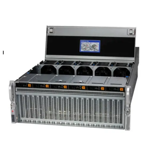
High-performance GPU servers like the NVIDIA DGX H100 and DGX H200 incorporate sophisticated internal networking alongside external fabric connectivity:
NVLink Internal Fabric: Within a server, NVIDIA GPUs connect via NVLink, providing 600-900 GB/s of bidirectional bandwidth between each GPU pair. This internal fabric handles intra-server communication with vastly higher bandwidth and lower latency than any external network technology. Optimal workload partitioning places tightly coupled model components on GPUs within the same server, reserving external network bandwidth for inter-server communication.
Dual-Port Network Adapters: Production GPU servers should include redundant network connectivity, typically via dual-port InfiniBand adapters or Ethernet NICs. This redundancy provides both fault tolerance and increased bandwidth for communication-intensive workloads. NVIDIA ConnectX adapters integrate seamlessly with GPU server platforms, providing hardware RDMA offload that reduces CPU overhead for network operations.
Bandwidth Sizing: The external network bandwidth required per GPU server depends on model architecture, batch size, and parallelization strategy. As a general guideline, each GPU generating 300-600 GB/s of NVLink traffic typically requires 200-400 Gbps of external bandwidth for efficient distributed training. This ratio ensures external network connectivity doesn’t throttle training performance while avoiding wasteful overprovisioning.
Storage Integration and Data Pipeline Design
AI training performance depends not only on compute and interconnect but also on efficient data delivery from storage systems to GPUs. The data pipeline must sustain throughput sufficient to keep GPUs constantly supplied with training data, avoiding idle time that wastes expensive compute resources.
Parallel File Systems: Large-scale AI deployments typically utilize parallel file systems like Lustre, GPFS, or BeeGFS that aggregate bandwidth from multiple storage servers. These file systems leverage the same high-speed networking that connects GPU servers, enabling storage bandwidth to scale linearly with cluster size. A well-designed parallel file system can deliver hundreds of GB/s of aggregate throughput, sufficient to feed thousands of GPUs.
NVMe-over-Fabrics Storage: For latency-sensitive storage access, NVMe-oF protocols running over InfiniBand or RoCE provide remote NVMe storage with performance approaching local PCIe SSDs. This capability enables disaggregated storage architectures where high-capacity NVMe arrays serve multiple GPU servers, improving utilization and simplifying management compared to local storage in each compute node.
Dataset Caching Strategies: Training data often resides in lower-tier storage initially, requiring transfer to high-performance tiers before training. Sophisticated data pipeline designs employ multi-tier caching:
- Local NVMe SSDs cache active working set for fastest access
- Mid-tier parallel file systems cache full training datasets
- Low-tier object storage retains historical datasets and checkpoints
This tiered approach balances performance, capacity, and cost while ensuring training workloads achieve maximum throughput.
Reference Architectures
Small-Scale Research Cluster (64-256 GPUs):
- 8-32x GPU servers with 4-8 GPUs each
- Single leaf InfiniBand switch (NVIDIA Quantum-2 QM9700)
- Mellanox MMA4Z00-NS400 transceivers for server connections
- 10-20x storage servers with NVMe-oF
- Total network bandwidth: 6.4-12.8 Tbps
Mid-Scale Production Cluster (256-1024 GPUs):
- 32-128x GPU servers
- 2-4x leaf InfiniBand switches
- 2x spine InfiniBand switches (NVIDIA Quantum-2 QM9790)
- Dual-homed servers for redundancy
- 40-80x storage servers
- Total network bandwidth: 25.6-51.2 Tbps
Large-Scale Supercomputing Cluster (1024+ GPUs):
- 128+ GPU servers
- 8-16x leaf switches in access layer
- 4-8x spine switches in aggregation layer
- 2-4x core switches for campus interconnection
- In-network computing acceleration (SHARP)
- 100+ storage servers with tiered architecture
- Total network bandwidth: 100+ Tbps
Performance Optimization and Troubleshooting
Bandwidth Utilization Analysis
Maximizing the investment in 400G optical transceivers requires ensuring applications fully utilize available bandwidth. Several factors commonly prevent optimal utilization:
Application-Level Bottlenecks: Training frameworks must be properly configured to leverage distributed computing capabilities. Parameters like batch size, gradient accumulation steps, and parallelization strategy dramatically impact network utilization. Frameworks like PyTorch and TensorFlow include profiling tools that reveal network communication patterns and identify optimization opportunities.
Imbalanced Traffic Patterns: Certain parallelization strategies create imbalanced traffic where some links carry significantly more traffic than others. Adaptive routing in InfiniBand helps mitigate this issue, but application-level optimizations like careful device placement and communication scheduling prove more effective for severe imbalances.
Protocol Overhead: RDMA protocols add minimal overhead, but misconfigurations can introduce unexpected latency. Organizations should validate that RDMA offload features are properly enabled on network adapters and that unnecessary protocol layers aren’t intercepting RDMA traffic.
Common Issues and Resolution
Link Flapping: Intermittent link failures often indicate optical issues—dirty connectors, damaged cables, or marginal transceivers. Systematic troubleshooting includes:
- Inspect all fiber connectors using microscope or automated inspection tools
- Clean contaminated connectors using appropriate cleaning methods
- Measure optical power levels and compare against transceiver specifications
- Check for bent or damaged fibers in cable assemblies
- Verify transceiver firmware is current
- Monitor bit error rates which may indicate marginal optical budgets
Performance Degradation: If network throughput fails to meet expectations, investigation should include:
- Verify actual link speeds match expected 400G rates
- Check for unexpected packet loss or retransmissions
- Confirm flow control mechanisms are operating correctly
- Review switch buffer utilization for signs of congestion
- Analyze traffic patterns to identify hotspots or imbalances
- Validate that network adapter offload features are enabled
Compatibility Issues: Mixing transceivers and switches from different vendors can occasionally cause interoperability problems despite adherence to standards. When compatibility issues arise:
- Update switch and transceiver firmware to latest versions
- Review vendor compatibility matrices
- Test specific transceiver/switch combinations in lab before production deployment
- Engage vendor technical support for assistance with stubborn issues
- Consider maintaining single-vendor solutions for critical production infrastructure
Future Outlook and Technology Roadmap
800G and Beyond
The networking industry has already standardized 800 Gigabit Ethernet (IEEE 802.3ck) and InfiniBand XDR (Extended Data Rate), with products entering the market in 2024-2025. These next-generation technologies maintain backward compatibility with 400G while doubling bandwidth to accommodate ever-growing AI model sizes and training workload demands.
800G transceivers will initially target long-reach applications where PAM4 signaling at 100 Gbps per lane provides acceptable performance characteristics. As technology matures, 800G SR8 variants using 100 Gbps lanes over multimode fiber will enable short-reach connectivity suitable for intra-cluster communications. Organizations planning infrastructure today should consider cable plant capable of supporting future 800G deployments, avoiding costly rework when upgrading from 400G.
Co-Packaged Optics
Traditional pluggable transceiver designs place optical components in modules that plug into switch faceplates, introducing electrical signal path lengths that limit performance. Co-packaged optics (CPO) represents a radical architectural shift where optical engines integrate directly with switch silicon, eliminating electrical transmission challenges and dramatically reducing power consumption.
CPO technology promises to enable switch ports operating at 1.6 Tbps and beyond while reducing power per bit by 50% or more compared to pluggable alternatives. Several major switch vendors have announced CPO product development programs, with volume availability expected in 2025-2026. The transition to CPO will initially focus on spine and core switch layers where port count and bandwidth density provide maximum benefit, with leaf switches likely continuing to use pluggable transceivers for flexibility.
Linear Drive Optics and Power Efficiency
As network speeds increase, transceiver power consumption threatens to become a limiting factor in data center design. Traditional transceivers employ digital signal processing (DSP) to compensate for transmission impairments, consuming significant power for equalization, error correction, and other processing functions.
Linear drive optics eliminate most DSP processing by utilizing high-quality optical components and simplified modulation schemes that require minimal signal processing. This approach reduces transceiver power consumption by 30-50% while maintaining equivalent performance and reach. Organizations building new infrastructure should prioritize transceivers featuring linear drive technology to minimize operational costs and thermal management challenges.
Best Practices for Procurement and Deployment
Vendor Selection Criteria
Choosing optical transceiver suppliers requires evaluation across multiple dimensions:
Quality and Reliability: Request MTBF (Mean Time Between Failures) data and seek references from existing customers. Transceivers from established manufacturers typically demonstrate superior reliability compared to lower-cost alternatives, justifying premium pricing through reduced operational costs.
Compatibility Validation: Verify transceiver compatibility with specific switch models before procurement. While standards compliance should ensure interoperability, real-world compatibility issues occasionally arise. Request vendor compatibility matrices and consider purchasing sample quantities for testing before large-scale deployments.
Support and Warranty: Evaluate vendor support capabilities including technical assistance availability, RMA (Return Merchandise Authorization) process efficiency, and warranty terms. Premium vendors typically offer advance replacement programs that ship replacement units before receiving failed modules, minimizing downtime.
Supply Chain Resilience: Recent global supply chain disruptions highlight the importance of supplier diversification and inventory management. Organizations should qualify multiple transceiver sources for critical components and maintain strategic inventory buffers to avoid deployment delays from supply constraints.
Testing and Validation Procedures
Comprehensive testing before production deployment identifies potential issues early when they’re easiest to resolve:
Optical Power Budget Validation: Measure transmit and receive optical power levels, verifying they fall within transceiver specifications with adequate margin. Marginal optical budgets may work initially but fail prematurely as components age or environmental conditions change.
Bit Error Rate Testing: Perform extended BER testing over days or weeks to identify intermittent issues that might not appear in short-duration tests. BER thresholds should meet or exceed 10^-12 for production deployment, with no errors observed during extended testing.
Environmental Stress Testing: Validate transceiver operation across full temperature ranges, humidity levels, and vibration profiles expected in production. Some transceivers exhibit temperature-dependent performance variations that could impact link reliability under extreme conditions.
Interoperability Testing: If deploying multi-vendor environments, thoroughly test all vendor combinations before production rollout. Create test matrices covering all planned component combinations and document any compatibility constraints discovered.
Frequently Asked Questions
What is the difference between 400G Ethernet and 400G InfiniBand transceivers?
While both operate at 400 Gbps, Ethernet and InfiniBand transceivers serve different protocols with distinct characteristics. InfiniBand transceivers like the Mellanox MMA4Z00-NS400 connect exclusively to InfiniBand switches and network adapters, leveraging InfiniBand’s low-latency, lossless architecture optimized for HPC and AI workloads. Ethernet transceivers work with standard Ethernet switches supporting protocols like RoCEv2 for RDMA capabilities. InfiniBand generally delivers lower latency and more predictable performance, while Ethernet offers broader ecosystem compatibility and operational familiarity.
Can I mix different 400G transceiver types in the same network?
Mixing transceiver types (SR8, DR4, FR4, etc.) is common and expected in most networks, with different types serving different reach requirements. However, each link must use identical transceivers on both ends—you cannot connect an SR8 transceiver to a DR4 transceiver. Within a network fabric, leaf switches might use SR8 transceivers for server connections while employing DR4 or FR4 transceivers for spine uplinks based on distance requirements.
How do I calculate the number of 400G ports needed for my AI cluster?
Port count calculations should consider several factors: number of GPU servers, network adapter configuration per server (single vs. dual-port), oversubscription ratio tolerance, redundancy requirements, and growth projections. As a starting point, a non-oversubscribed design requires one leaf switch port per server network adapter plus sufficient uplinks to carry aggregate traffic to spine layer. Organizations tolerating modest oversubscription (2:1 or 3:1) can reduce port counts proportionally. Factor in 20-30% growth capacity to avoid premature infrastructure upgrades.
What maintenance is required for 400G optical transceivers?
Optical transceivers require minimal maintenance under normal operating conditions. Key maintenance activities include: periodic connector inspection and cleaning (quarterly or when disturbed), firmware updates to address bugs or add features (as released by vendors), environmental monitoring to ensure transceivers operate within temperature specifications, and optical power level monitoring to detect degradation trends. Failed transceivers should be replaced promptly to maintain redundancy levels. Most transceivers include digital diagnostic monitoring (DDM) capabilities reporting temperature, optical power, and other parameters useful for predictive maintenance.
Are 400G transceivers backward compatible with 100G or 200G infrastructure?
QSFP-DD transceivers maintain electrical backward compatibility with QSFP28 (100G) ports through mechanical design that allows QSFP-DD modules to insert into QSFP28 cages. However, 400G transceivers cannot operate at 100G speeds—compatibility is purely physical. Some switches support mixed-speed configurations where different ports operate at different rates, but this requires explicit switch support. Organizations should plan clear migration paths from existing 100G or 200G infrastructure to 400G rather than expecting seamless interoperability.
What cable types are required for different 400G transceiver variants?
Cable requirements depend on transceiver type: SR8 transceivers require 12-fiber or 24-fiber OM3/OM4/OM5 multimode cable with MPO connectors. DR4 transceivers use single-mode fiber with duplex LC connectors or 8-fiber MPO for breakout configurations. FR4 and LR4 variants employ single-mode fiber with LC or MPO connectors depending on implementation. Organizations should align cable plant installation with planned transceiver types, though deploying single-mode infrastructure provides maximum flexibility for supporting various transceiver types and future upgrades.
How much power do 400G transceivers consume, and what are thermal implications?
400G transceiver power consumption varies by type, ranging from 10-15W for typical implementations. SR8 and DR4 variants typically consume 10-12W, while longer-reach FR4 and LR4 types may require 12-15W due to additional optical amplification. In high-density switches with 32-64 ports, aggregate transceiver power can exceed 500W, generating significant heat that cooling systems must remove. Data center designers should account for transceiver thermal load when sizing cooling capacity, ensuring adequate airflow and verifying transceiver operating temperatures remain within specifications.
What is the typical lifespan of a 400G optical transceiver?
Quality 400G transceivers from established manufacturers typically demonstrate 7-10 year operational lifespans under normal data center conditions. Actual lifespan depends on multiple factors including operating temperature, duty cycle, environmental conditions, and manufacturing quality. Transceivers operating continuously at elevated temperatures experience accelerated aging compared to those in well-cooled environments with moderate utilization. Most vendors offer 3-5 year warranties, though transceivers frequently outlast warranty periods with proper environmental management.
Do I need to match transceiver brands with switch manufacturers?
While many switch vendors recommend or require their branded transceivers for support eligibility, industry-standard 400G transceivers from reputable third-party suppliers generally work reliably when properly validated. Organizations should review switch vendor support policies carefully—some maintain approved third-party transceiver lists while others may decline support for issues involving non-branded optics. Mission-critical production environments often justify OEM transceiver premiums for comprehensive vendor support, while development and test environments can successfully employ qualified third-party alternatives to reduce costs.
How do I troubleshoot poor performance with 400G transceivers?
Performance troubleshooting should follow a systematic approach: First, verify link establishment and negotiated speed matches expected 400G rate. Check digital diagnostic monitoring (DDM) data for optical power levels, temperature, and error counters. Inspect fiber connectors for contamination or damage. Review switch logs for link flap events or error messages. Measure actual throughput using network performance tools to quantify degradation. Compare performance against identical reference links to isolate problematic components. Swap suspect transceivers or cables with known-good units to identify failed components. Engage vendor technical support for persistent issues or when advanced diagnostic tools are required.
Last update at December 2025